We cordially invite you to attend our upcoming Ground Breaker's User Group (GBUG) Meeting at the Royal Woodbine Golf Club on Thursday, January 12th, 2012 for an evening of fun, food and great technology presentations!
Event Details:
Venue Name: Royal Woodbine Golf Club (Lower Level)
Address: 195 Galaxy Blvd.Toronto, ON M9W 6R7
Date: Thursday January 12th, 2012
Time: 6:30 PM to 9:00 PM EST
Parking: FREE
Agenda:
Introduction - Brock Smith & Prem Joseph of SolidCAD
Autodesk Infrastructure New Modeller Suite - Jeff Lyons, Cole Engineering.
• Learn how Autodesk's New Infrastructure Modeler can be used by Consulting Engineering firms and Municipal Governments.
• Observe best practices from the conceptual design stage up to the finished model.
Autodesk Infrastructure Design Suites and Department Of Transports (DOTs) - Rick Larson Applications Engineer, Transportation North America - AEC Solutions Autodesk.
• Detailed discussion on Autodesk's involvement with the DOT's in the U.S. (ie. Wisconsin Department of transport and Caltrans) and how it relates to MTO here in Ontario.
• Q&A.
To register contact Samantha Tran at 1-877-438-2231 Ext. 243 or via email at stran@solidcad.ca.
Thank You and we look forward to seeing you all in the New Year!
Want to become a GBUG Member?
To become a GBUG member, please contact Samantha Tran at stran@solidcad.ca

Tuesday, January 3, 2012

Sunday, March 13, 2011
Using Civil 3D Expressions with Profile Design Check Parameters
While our last post looked at using an Expression to control the labels of our pipe lengths which is typically used at the final drawing production stage, this post deals with using Expressions to help at the preliminary design stage. 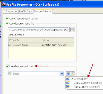
Click the ADD button to add it to the set
Click Apply and OK twice.
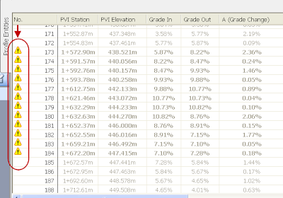
Select the Profile, right click and select the Edit Profile Geometry command and from the Profile Grid View button the violations will be displayed.

Here is the scenario...
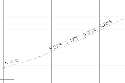
The client is working on a 15 kilometre road reconstruction project that has a lot of vertical grade difference and needs to identify areas of the existing road that has a vertical grade of 6% or greater that may be considered for improvements based on the jurisdictions requirements.
How do we quickly identify these areas on a Civil3D profile?
By using the Expressions dialogue box and the Profile Design Check Set functions !
Here's how we do it.
Once you have your Civil3D Surface Profile and Profile View created select the profile and right click>Profile Properties.

Click on the Design Criteria tab and check the Use design criteria file check box


Click on the Create New in the Use Design Check Set section
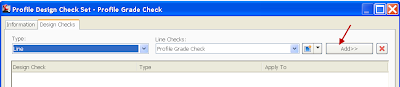
Set the Type to Line and select then the Create New button from the pull down

Enter a name for the Design Check

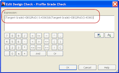
Using the Insert Properties and Functions buttons add the following in the Expressions section and click OK


We should have the slope percent in degrees so lets enter into our Expression the equivalent of 6% in degrees which is 3.43363.

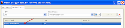
Click the ADD button to add it to the set


Click Apply and OK twice.
Select the Profile, right click and select the Edit Profile Geometry command and from the Profile Grid View button the violations will be displayed.


This Expression will check the profile and flag as a violation any grade greater than 6% or greater than -6%.

Don’t forget, even though we used Expressions this is still a Design Check so the function will be located under the Design Check Sets of the Profile Settings.
Stay tuned for more fun with Expressions!!
dh
Tuesday, February 22, 2011
Civil 3D Label Styles-Using Expressions
For every project we use either the out of the box styles or create new styles to meet the specific requirements of the company we work for or the project we are working on
Once they are included in our template we have everything covered, right?
Once they are included in our template we have everything covered, right?
But what if you need to display a property of an object that isn’t available under the Label Style Composer? Or maybe we want to display the label in a different way based on a certain value of the object?
Over the next few posts we are going to dig into the use and application of Label Expressions that can be applied in a variety of simple and complex labeling situations.
First, let’s take a quick look at the fundamentals of the Expressions.
Expressions are located under the Settings tab of the Toolspace, under the Label Styles folder.

The New Component dialogue box consists of a number of components that are used to create the Expression

1. In the Name field enter a relevant, identifiable name for your Expression
2. The Expression field will contain all the formulas and properties as the Expression is developed.
3. Buttons that may be used to aid in the development of the Expression (you can enter by the keyboard if you prefer)
4. The available object properties that may be inserted in the Expression field.
5. Functions that may be used in the development of the Expression
6. Chose how the results of the Expression are to be formatted. Usually always Double. (Unitless)
As an example let’s create an Expression that will truncate a pipe length label to the nearest 0.50 metre.
To create the Expression right click on the “Expressions” and select New

As an example let’s create an Expression that will truncate the pipe length label to the nearest 0.50 metre.

1. In the dialogue box enter a name and description for the Expression that reflects the resultant label style.
2. Pick the Formula button to expand the Expression Functions, in our case select the ROUND function

This inserts the ROUND function to the Expression window.

Next we need to add the Object Property by picking the Object the Properties button and picking the appropriate Property.
In our case we will select 2D Length-Center to Center which is automatically inserted into the Expression window.


Now we just need to add a little more math to complete the Expression and then click OK.


The new Expression will be displayed in the Previewwindow of the Toolspace>Settings tab under the Pipe Label Styles and is now available to be applied to a pipe label

To add the Expression to the Label Style create a New pipe Label by copying and editing an existing style.

Copy the default Length Description and Slope label style and rename it Rounded Length and Slope

Select the Layout tab and in the Text section on the Contents row pick the corresponding cell in the Value column and pick the Ellipse button to access the Text Component Editor

In the preview window of the Component editor highlight the “2D Length…” string and press delete to remove it from the label

In the Properties section pick the down arrow and locate the “Pipe Length to Nearest 0.5m” Expression that was created, set the Precision to 0.1 and click the UPDATE arrow to update the label in the preview window

Click OK twice to closer the Component Editor and Label Composer.
Apply the new pipe label to the pipe object and the center to center length with be rounded to the nearest 0.50m
Pipe Label

Actual Pipe Properties

Now that we have the basics down our next post will address a few more complicated Expressions and their applications.
cheers
dh
Wednesday, January 19, 2011
Civil 3D Object Tooltips
If you’ve been using Civil 3D for a while, you’re probably loving the object tooltips! The reason for this blog post is the few support calls we’ve received recently.
 Notice the “New Entity Tooltip State”
The typical technical call is along the lines of “Some of our project Surfaces / objects are not displaying the Tooltips? – help!!!”
Before I get into solving the problem, let’s explore a bit more on tooltips.
The following are from Civil 3D help documents:
There are 2 types of tooltips for C3D objects: proximity and rollover
Rollover
A rollover tooltip displays information about an object when you hover the cursor directly over it. If the object highlighting setting is on, the object will be highlighted when this tooltip is displayed.
Proximity
A proximity tooltip displays information about the current location of the cursor with respect to one or more objects in the drawing. More specifically, it displays information about the proximity of the cursor to the objects. These tooltips are displayed without having to hover the cursor over any specific entity in the drawing.
The most important object information is displayed at the beginning of the tooltip. For alignments and surfaces, the tooltip displays the station/offset information for the closest alignment to the cursor and the elevation of the topmost surface.
If you keep your cursor in the same location, additional information is displayed in an expanded tooltip that shows up to four more items. Which items are displayed depends upon the objects in the drawing and whether tooltips are enabled for that object. If there are five alignments and five surfaces in the drawing, for example, the proximity tooltip will display three alignments and three surfaces. Alignments are shown in order of proximity to the cursor. Surfaces are shown in order from highest elevation, to lowest elevation.
Ok, that’s enough “help”; let me get back to the technical support question.
On the Toolspace Settings tab, right-click Surface --> Edit Feature Settings
 Notice the “New Entity Tooltip State”
 On: Sets the default state of tooltips for new objects to be turned on.
Off: Sets the default state of tooltips for new objects to be turned off.
Click OK and voila the tooltips are back on all surfaces.
Well, the C3D world changes to a certain extent every release, mostly for the better, but sometimes the changes are painful :)
Wednesday, January 5, 2011

The First Ground Breakers Meeting of 2011
Wednesday, January 19, 2011
7:00pm - 9:30pm
Brix Napa Valley Grille & Wine Bar
230 Commerce Valley Drive, East #1
Thornhill/Richmond Hill L3T 7Y3
Meeting Topics
- Introduction to the Meeting: Brian McCorriston, CAD MicroSolutions
- BIM for Civil Engineering: Derek Gauer, IBI Group
- Autodesk Subassembly Composer: Prem Joseph, CAD MicroSolutions
- User Group Executive Committe Selection
- Topics of Interest for the Next User Group Meeting
- Networking Opportunities
Thursday, April 22, 2010
Autodesk 2011 Solutions Event
Keep Costs Down and Increase Productivity
Let CAD MicroSolutions show you how to turn your business challenges into opportunities at the Autodesk 2011 Solutions Event - May 7, 2010.
Sessions Include:
Friday, May 7, 2010
Toronto Congress Centre
8:30am - 2:00pm
Lunch Provided
For more information or to register visit www.cadmicro.com/learn2011
We look forward to seeing you there!
Let CAD MicroSolutions show you how to turn your business challenges into opportunities at the Autodesk 2011 Solutions Event - May 7, 2010.
Sessions Include:
- AutoCAD Civil 3D: What's New & Best Practices
- Land Development Grading, Storm Sewer Design using AutoCAD Civil 3D & Hydraflow
- Mi Symmetry: A Mobile Solution of Integrated Geospatial Data Utilizing SQL 2008 Spatial, AutoCAD Map & AutoCAD MapGuide
Friday, May 7, 2010
Toronto Congress Centre
8:30am - 2:00pm
Lunch Provided
For more information or to register visit www.cadmicro.com/learn2011
We look forward to seeing you there!
Thursday, December 17, 2009
Autodesk and Trimble Create AutoCAD Civil 3D Data Exchange Tool
Autodesk and Trimble Create AutoCAD Civil 3D Data Exchange Tool to Help Break Down Barrier Between Engineering and Construction
Extension Enables Automated Data Exchange Between AutoCAD Civil 3D Model and Trimble Construction Solutions
SUNNYVALE and SAN RAFAEL, Calif., Oct. 6, 2009 — Trimble (NASDAQ: TRMB) and Autodesk, Inc. (NASDAQ: ADSK) announced that they have collaborated to develop a fully automated data exchange tool enabling information from an AutoCAD Civil 3D model to be directly imported into the Trimble Business Center-HCE (Heavy Construction Edition) data management software.
The new, free*, Web-downloadable software extension, called the AutoCAD Civil 3D Importer for Trimble Business Center-HCE, provides the ability to import DWG files that contain AutoCAD Civil 3D native design objects into the Trimble Business Center-HCE software. The AutoCAD Civil 3D model information is then used by the Trimble Business Center-HCE to prepare, manage and distribute data for use with Trimble's range of site positioning and grade control products for earthmoving, grading and finishing operations. Using the extension, contractors can realize a number of benefits, including:
* Reduced data preparation time and costs: Minimizing the need to recreate design information helps reduce data preparation time and supports the faster delivery of updated design information to the field as a result of design changes, which is especially beneficial on highways projects where design revisions occur frequently.
* Rich, first-hand information to the field: The ability to retain the intelligence of the Civil 3D source model incorporating corridor model sections, alignments, station equations, profiles, feature lines, finished grade and subgrade surface information and advanced point objects provides more detailed information and higher precision; the construction-ready 3D models can be more quickly leveraged by Trimble machine control and site positioning systems.
* Full DWG compatibility: Improved DWG file format support (including Real DWG) allows for extraction of both native CAD data and Civil 3D model data (which would previously have been lost) delivering enhanced compatibility with the Autodesk DWG file standards.
* More simplified workflow: Now instead of using intermediary and often less comprehensive file formats such as LandXML or basic CAD files for exchange of information between the engineer and contractor, the engineer can simply save the project and deliver the native design file without needing to think about saving the file out to an alternative format, which is immediately detached from the source design.
"Our new utility is a bridge that makes rich Civil 3D model information available to contractors who are going to grade the site," said Jim Lynch, vice president of marketing, Autodesk Architecture, Engineering and Construction Solutions. "With this new software extension, which transfers the Civil 3D model data into the Trimble Business Center data management software, we are bringing the benefits of a model-centric approach all the way to the job site. Before grading starts, contractors want to verify that the model they are sending into the field is appropriate for construction. That's where this new utility contributes; helping to reduce errors, save time and increase accuracy."
"Streamlining and optimizing the flow of data and information between the engineering design and the construction communities is a key motivation we share with Autodesk," said Roz Buick, general manager, Heavy and Highway Division, Trimble. "Our new collaboration creates a powerful data exchange extension that allows the information contained in Civil 3D models to flow more easily and efficiently out to the machine control and site positioning systems. Now contractors can take Civil 3D information and create models designed to optimize the use of Trimble site positioning and machine control solutions."
AutoCAD Civil 3D software, the building information modeling (BIM) solution for civil engineering, helps project teams create, predict and deliver transportation, land development and environmental projects more efficiently. AutoCAD Civil 3D helps civil engineers explore more what-if scenarios and optimize project performance with visualization and analysis tools such as geospatial and stormwater analysis, quantity takeoff and interactive 3D simulations.
Trimble Business Center-HCE software supports construction data preparation and intelligently manages the provision of data to and from construction field crews. The software puts emphasis on efficient data management for multiple field crews and machines operating on a site over the lifetime of the project. Using Trimble Business Center-HCE, contractors can import, review and analyze digital design information or field generated data and easily assign, manage and track that information through the lifetime of a construction project.
To download the free* AutoCAD Civil 3D Importer for Trimble Business Center-HCE import software extension visit: www.autodesk.com/civil3d-trimble or www.trimble.com/tbc-hce. For more information on the Trimble Business Center-HCE data management software visit: http://www.trimble.com/tbc-hce.shtml. For more information on Autodesk Civil 3D visit: www.autodesk.com/civil3d.
Subscribe to:
Posts (Atom)